Unifi Network - Setup VLANs including IoT and access to Pi-hole
Here I describe which networks/VLANs and WiFi networks I have created. And how I configured the firewall and added a rule that allows the Pi-hole from the SERVER-VLAN to be used by devices in other VLANs such as the CLIENT-VLAN and IOT-VLAN.
I replaced my old Unifi Security Gateway (USG) with a Unifi Dream Machine Pro (UDM-Pro) and made the choice to build everything from scratch and not migrate the settings. So all settings are set by default and from there I make the necessary adjustments.
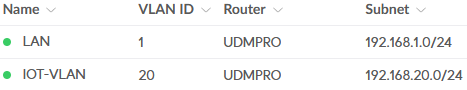
I have created the following networks:
- LAN (this is the default network and renamed to LAN) - very trusted - this contains all network equipment
- SERVER-VLAN - very trusted - this contains servers and a NAS
- CLIENT-VLAN - trusted - this contains clients like desktops, laptops, tablets and phones
- IOT-VLAN - not trusted - this contains smart(home) devices and media players
- GUEST-VLAN - not trusted - this contains not trusted clients including devices from work
Make sure the device you use to configure your Unifi Network remains in LAN until you finish configuring the firewall (see at the very bottom).
Setup Network
First I determined which VLAN ID each VLAN should have. For example for the IOT-VLAN I use VLAN ID 20.
This number will match the Gateway IP/Subnet - 192.168.20.0/24.
Perform the following steps to create the IOT-VLAN:
- Go to
SettingsandNetworks - Click
New Virtual Network:- Network Name:
IOT-VLAN - Uncheck
Auto-Scale Networkand change the Host Address to192.168.20.1
Advanced Configuration - Click
Manual- everything is set by default except what I described below - VLAN ID:
20 - Multicast DNS: please read Unifi Network - Setup Chromecast between VLANs for more information
DHCP - DHCP Range Start:
192.168.20.150 - DHCP Range Stop:
192.168.20.254
I have chosen a DHCP range between 150 and 254. This gives me the possibility to use all IP addresses before 150 as fixed IP addresses.
- Expand
Show optionsafter DHCP Service Management- In my case I unchecked
AutoafterDNS Serverand added the IP address of my Pi-hole
- In my case I unchecked
- Domain Name:
home.arpaHome.ARPA has been specifically created to handle “home” or “small business” name queries by shunting it to “black holes” early in the hops.
- Network Name:
- Click
Add
Repeat the above steps for any other vlan.
I configured the GUEST-VLAN the same, so I did not enable the
Isolation Networksetting. Just like the other vlans, the GUEST-VLAN is already separated from other vlans via the firewall (see below). But you can also choose to use this setting and the Hotspot portal and Guest WIFi.
Port Management
Now that the networks/vlans have been created, we can adjust the switch port settings. With this we ensure that wired devices use the correct VLAN and, for example, will receive the correct IP address.
Do not change the
Native VLAN / Networksetting of the ports which are connected to the gateway, other switches or access points, leave it set toLANand theTagged VLAN Managementsetting toAllow All.
For wireless devices, we will create the corresponding WiFi networks in the next part.
- Go to
Ports(or alternatively go toUnifi Devices, click on a switch or the UDM and click thePort Managerbutton) - Go to tab
Ports, if this is not already selected - Now you can select the port of which you want to change the port profile
For example, I selected port 8 and changed the following:
- Name: P1Reader - this is the name of the IoT device
- Native VLAN / Network: IOT-VLAN
- PoE: Personally, I turn off PoE if the device does not need power
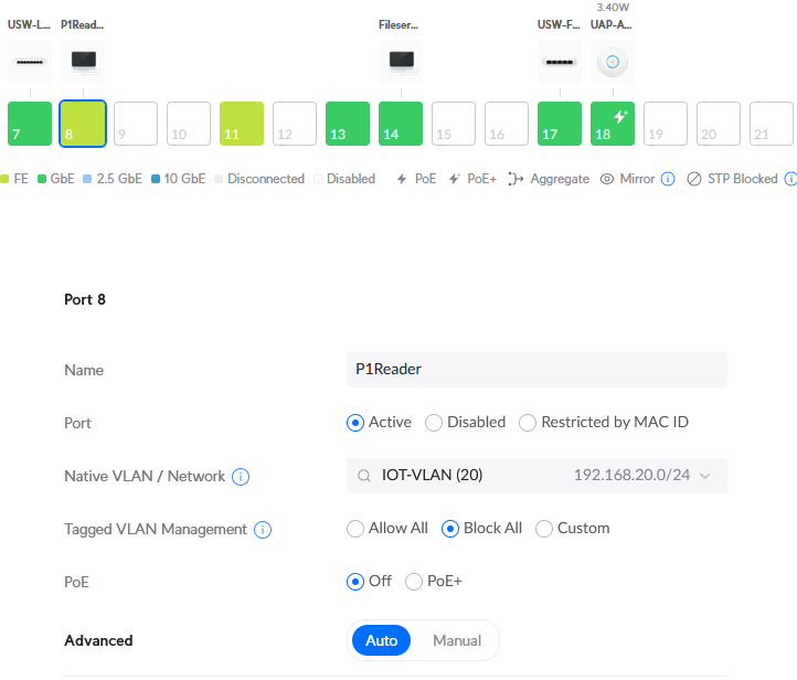
And finally click Apply Changes.
Repeat this for all ports for which it is necessary to change the port settings.
To check if the port settings are working properly, do the following:
- Go to
Client Devices - And there is the P1Reader within the IOT-VLAN network and a corresponding IP address:

Columns like
Network(the IOT-VLAN field) can be added in theDisplay Options.
Optionally you can click on the device and go to Settings and give it a fixed IP address (which I did in this example).
Setup WiFi
To ensure that wireless devices connect to the correct network, I have created three WiFi networks:
- WiFi-Client
- WiFi-IoT
- WiFi-Guest
Everything is set by default except what I described below.
- Go to
SettingsandWiFi - Click
Create New:- Name: for example
WiFi-IoT - Password: Your password
- Network: for example
IOT-VLAN- or linkWiFi-ClienttoCLIENT-VLANandWiFi-GuesttoGUEST-VLAN
Advanced Configuration- Click
Manual - Client Device Isolation: I have enabled this only for the
WiFi-Guestnetwork - WiFi Speed Limit:
Default- for theWiFi-Guestnetwork I have created a guest profile that limits the bandwidth slightly - Multicast Enhancement and Multicast and Broadcast Control: please read Unifi Network - Setup Chromecast between VLANs for more information
- MAC Address Filter: I have enabled the filter for
WiFi-ClientandWiFi-IoT - Security Protocol: use
WPA2for backwards compatibility, so I usedWPA2forWiFi-IoTenWPA2/WPA3forWiFi-GuestandWiFi-Client. At some point I will completely switch toWPA3 - Group Rekey Interval:
Enable 3600 seconds- for increased security
- Click
- Name: for example
Personally, I think it’s a good thing to consciously give access to certain devices. That’s why I keep a list of MAC addresses that I give access. About the option to hide the WiFi name: opinions differ that a hidden WiFi network provides more security, it therefore remains a personal choice.
And finally click Add WiFi Network.
Repeat the above steps for any other WiFi network.
Setup Firewall
There are a number of devices I want to deprive of access to the Internet, which I have described further in this note. This mainly concerns IoT devices.
To make the vlans work properly the first rule I created is to allow established/related sessions from client devices. Then I made sure traffic between the networks is no longer possible. Blocking inter-VLAN routing is also described by Ubiquiti here.
You can also choose to use Traffic Management instead of firewall rules. Firewall rules are generally used to match on specific ports and IP addresses. Traffic rules can match on categories such as an App or Domain. Personally, I have made the choice to use firewall rules.
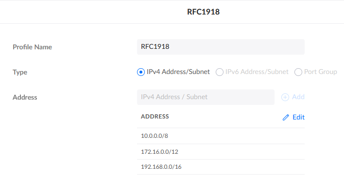
First create the IP Group needed for blocking inter-VLAN routing:
- Go to
SettingsandProfiles - Go to tab
IP Groups - Click
Create New:- Profile Name:
RFC1918 - Type:
IPv4 Address/Subnet - Address: add
10.0.0.0/8,172.16.0.0/12, and192.168.0.0/16
- Profile Name:
- Click
Add
You can now use this IP group when creating the firewall rule.
- Go to
SettingsandSecurity - Go to tab
Firewall Rules - Go to
LANrules
Rule allow established/related sessions
- Click
Create Entry:- Type:
LAN In - Name:
allow established/related sessions - Action:
Accept - Protocol:
AllandBefore Predefinedis enabled
Advanced- Click
Manual - Match State:
EstablishedandRelatedare enabled
- Click
- Type:
- Click
Add Rule
Rule drop traffic between vlans
- Click
Create Entry:- Type:
LAN In - Name:
drop traffic between vlans - Action:
Drop - Protocol:
AllandBefore Predefinedis enabled
Source- Source Type:
Port/IP Group - Address Group:
RFC1918
Destination - Destination Type:
Port/IP Group - Address Group:
RFC1918
- Source Type:
- Type:
- Click
Add Rule
Now all vlans/networks are seperated from each other.
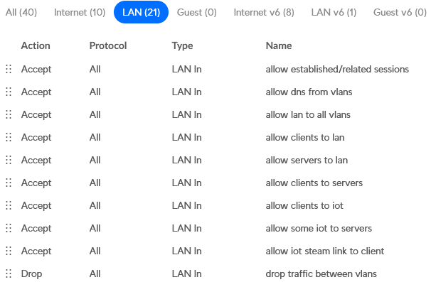
The rules below will make it possible that:
- All vlans has access to Pi-hole DNS
- LAN has access to all other networks
- CLIENT-VLAN has access to LAN (or make sure that you allow individual devices from the CLIENT-VLAN to manage LAN)
- CLIENT-VLAN has access to SERVER-VLAN
- CLIENT-VLAN has access to IOT-VLAN
- Some IOT-VLAN devices has access to SERVER-VLAN
This seems to me personally a good basis to start with. The next step may be to set up access between the vlans in more detail.
Rule allow dns from vlans
- Click
Create Entry:- Type:
LAN In - Name:
allow dns from vlans - Action:
Accept - Protocol:
AllandBefore Predefinedis enabled
Source- Source Type:
Port/IP Group - Address Group:
RFC1918
Destination - Destination Type:
Port/IP Group - Address Group: create a new
IP Groupand add the IP address of your Pi-hole(s) - Port Group: create a new
Port Groupand add port53
- Source Type:
- Type:
- Click
Add Rule
Rule allow lan to all vlans
- Click
Create Entry:- Type:
LAN In - Name:
allow lan to all vlans - Action:
Accept - Protocol:
AllandBefore Predefinedis enabled
Source- Source Type:
Network - Network:
LAN - Network Type:
Ipv4 Subnet
Destination - Destination Type:
Port/IP Group - Ipv4 Address Group:
RFC1918
- Source Type:
- Type:
- Click
Add Rule
Rule allow clients to lan
- Click
Create Entry:- Type:
LAN In - Name:
allow clients to lan - Action:
Accept - Protocol:
AllandBefore Predefinedis enabled
Source- Source Type:
Network - Network:
CLIENT-VLAN - Network Type:
Ipv4 Subnet
Destination - Source Type:
Network - Network:
LAN - Network Type:
Ipv4 Subnet
- Source Type:
- Type:
- Click
Add Rule
Rule allow clients to servers
- Click
Create Entry:- Type:
LAN In - Name:
allow clients to servers - Action:
Accept - Protocol:
AllandBefore Predefinedis enabled
Source- Source Type:
Network - Network:
CLIENT-VLAN - Network Type:
Ipv4 Subnet
Destination - Source Type:
Network - Network:
SERVER-VLAN - Network Type:
Ipv4 Subnet
- Source Type:
- Type:
- Click
Add Rule
Rule allow clients to iot
- Click
Create Entry:- Type:
LAN In - Name:
allow clients to iot - Action:
Accept - Protocol:
AllandBefore Predefinedis enabled
Source- Source Type:
Network - Network:
CLIENT-VLAN - Network Type:
Ipv4 Subnet
Destination - Source Type:
Network - Network:
IOT-VLAN - Network Type:
Ipv4 Subnet
- Source Type:
- Type:
- Click
Add Rule
Rule allow some iot to servers
- Click
Create Entry:- Type:
LAN In - Name:
allow some iot to servers - Action:
Accept - Protocol:
AllandBefore Predefinedis enabled
Source- Source Type:
Port/IP Group - Ipv4 Address Group: create a new
IP Groupand add the IP address of some IoT device(s)
Destination - Destination Type:
Port/IP Group - Ipv4 Address Group: create a new
IP Groupand add the IP address of some server(s)
- Source Type:
- Type:
- Click
Add Rule
In this way I have created a few more rules. A number of things are accepted first and otherwise the traffic will be dropped between the vlans. The firewall rules then look like this:
Testing
Test if it works, for example with your mobile phone by temporarily connecting to the IoT WiFi network.
Read other notes
Tags
Notes mentioning this note
- Docker - Telegraf Container with Syslog Receiver Input Plugin
I found out that an IoT device (smart power strip) had the setting to communicatie with a syslog server and...
- Unifi Network - Replacing the USG with the UDM Pro
I finally replaced my old Unifi Security Gateway (USG) with a Unifi Dream Machine Pro (UDM-Pro).
- NixOS - Server Configuration and Switch to Podman
For some time now I have been looking for an interesting lightweight linux distribution that could replace Ubuntu
- Unifi Network - Block Internet Access for Specific Devices
I have a number of devices that I no longer want to give access to the internet.
- Unifi Network - Setup Chromecast between VLANs
Fortunately, it is nowadays very easy to use the Chromecast within different networks/vlans. All you have to do is make...
Comments
No comments found for this note.
Join the discussion for this note on this ticket. Comments appear on this page instantly.